
TL;DR
- Time waveform replication means playing recorded movement back on a test machine. Our EMA does this for dampers.
- On many machines, engineers correct and replay the file several times before the real test. On the EMA, the correction happens inside the controller, in real time.
- You can run built-in test types, waveforms the software generates, or your own profile, including vehicle telemetry.
- Current models handle 250 mm of stroke, up to 7,000 mm/s, 150 Hz and 100 G.
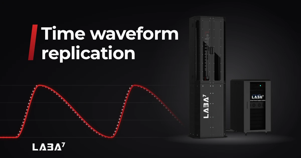
Engineers record how a damper moved on a vehicle, then play that movement back on a test machine. This is called time waveform replication (TWR), or road load data replay. In our software, it is called a track data test.
On many machines, the first playback is not accurate enough. The engineer compares what the machine did with what was asked. Then they correct the file and play it again. This repeats until results are close enough. On our electromagnetic (electrodynamic) damper test system, the EMA, it is a playback button.
What the EMA plays back?
The EMA moves the damper along its length, following the recorded movement. That movement can come from vehicle telemetry, a waveform generated in our software, or a profile you create yourself. An optional side load unit can also push on the damper from the side during a test.
The EMA does not recreate a whole car on a road. Testing complete cars or suspension corners, with wheel forces and body movement, is a different job.
Why other machines need extra rounds?
Most shock absorber test machines, ours included, correct their movement while they run. Engineers call this closed-loop control. Still, many engineers we talk to add extra correction rounds on hydraulic machines. The hours spent on those rounds are hours the machine is not producing data.
As we understand it, part of the reason is lag. On a hydraulic machine, force travels through oil and a valve. The system reacts with a delay and falls behind fast, sudden movements. That lag changes with amplitude, frequency and oil temperature. The extra rounds correct the file for it.
What we did instead?
Our R&D team spent a long time tuning the control algorithm. It had to be fast, and it had to compensate for the way a damper fights back. The result: correction happens inside the controller, during the run.
Standard motion controllers are built for general positioning and set conservatively. They cannot keep up with sudden spikes in damper force. Ours is written for damper testing. Even at extreme speeds and forces, it holds the requested velocity curve. Correct force data depends on it.
In numbers: velocity control bandwidth of about 300 Hz and force control bandwidth of about 640 Hz. The control loop runs at 21 kHz. Bandwidth is the fastest change the controller can follow. The loop rate is how often it checks and corrects.
Every controller has PID, even those behind hydraulic valves. It sets how fast and how strongly the controller reacts to a change. A damper’s resistance is not linear, so these settings matter.
Standard settings work for most dampers. Very stiff or very light dampers at extreme speeds may need adjustment. Control loop configuration is in the General settings of our shock dyno software. Once it is enabled, the user can adjust the PID algorithms. Detailed instructions come in a separate document supplied with the EMA.
How you load a test?
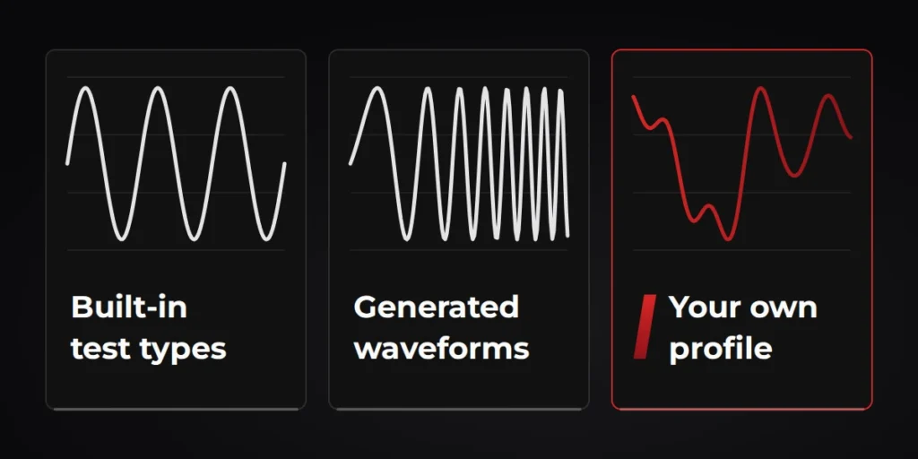
The EMA runs three kinds of input.
The first is the built-in test types. These include sine, constant velocity, constant acceleration, sawtooth, inverted sawtooth, sine-on-sine, impulse and free fall. You set stroke, speeds, frequency and other values in the software.
The second is waveforms the software generates for you. These are pink noise, linear and exponential sweeps, and linear and exponential chirps. You set the duration, stroke and frequency range.
The third is your own profile. A custom client waveform is any displacement profile you create on a computer, and the EMA replicates it. Track data is a profile recorded on a vehicle. Select the CSV format of your telemetry device, MoTeC for example, and the units, then select the file. You can filter it, trim it to one section, set the minimum position and apply a displacement multiplier.
Can you see what the machine actually did?
Yes. For any run, our shock dyno software can show the original waveform. It appears as a dotted line over the executed one.
Here is one of our tests.
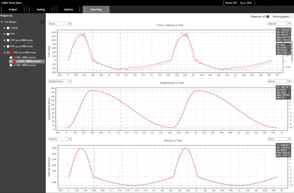
We ran a used Fox Factory internal bypass damper at over 5 m/s compression on the EMA (rebound was 1,500 mm/s and stroke 180 mm). The velocity and displacement traces sit on the commanded waveform. The dotted line in our software is the original request, and the executed motion follows it.
On the graphs, the executed displacement and velocity follow the dotted line through most of the cycle. The biggest gap is on the fast compression. The force line has steps and spikes, while the movement lines stay smooth.
Why it matters?
The first benefit is time. Without extra correction rounds, the machine spends its hours testing dampers.
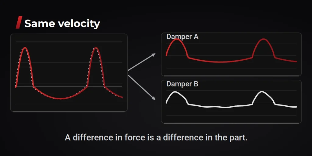
The second is comparability, and for us it is the more important one. Engineers compare dampers all the time: a new damper against a used one, or one setting against another. That comparison is only fair if the machine moves both dampers the same way. Then a difference in the force data is a difference in the part, not a difference in how the machine behaved.
Movement is not the only thing that changes results. Temperature does too. A damper warms up as it works, and its force changes with it. The EMA measures damper temperature during the test, with infrared and NTC sensors. So before comparing two runs, you can check whether they were done at the same temperature.
What fits?
Every profile has to fit the machine. Current EMA models handle:
- 250 mm of stroke
- velocity up to 7,000 mm/s
- test frequency up to 150 Hz
- acceleration up to 100 G
- peak force at 2 m/s of 10, 20 or 40 kN, depending on the model
A profile beyond these limits can be trimmed or scaled. It then becomes a modified test, not an exact copy of the recording. More on specs in our guide to reading a damper test rig spec sheet.
Have recorded damper data you would like to see on a damper test machine? Talk to us.
Our latest articles:
- LABA7 Opens 1,000 m² Facility to Build Next-Generation EMA Systems
- Time waveform replication on a damper: why we correct in real time
- What should I compare when buying a shock dyno: force, velocity, stroke, software and measurement accuracy?
- What a PVP Graph Hides?
- How to Read a Damper Test Rig Spec Sheet Without Being Misled?